|
|
|
Categories
|
|
Information
|
|
Featured Product
|
|
|
 |
|
|
There are currently no product reviews.
 ;
Good manual. It is complete and of high quality, both text and graphics. The schematics are with the original big size, so it can be viewed or printed without any loss of resulution and sharpness.
;
We needed a manual quickly...online it was available immediately, at a very low price. We loved the convenience!
;
Excellent!!
Got what I need and very fast!!
Thank You
;
One address for rare manuals.Very good copy. Thank you.
Your
Klaus Husse
;
All ok. I pay 5 $ and now i have 92 pages of good scaned service manual for my oooooold akai. Now i will try to repair it.
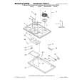
Technical Manual
MCC-1II
EXPLODED VIEW
1 17 2
3 4 5 15 10 6 18 7 11 16 8
MCC-1II Cabinet � Not for Sale
4 14 12 13
ITEM NO. DESCRIPTION 1. Front Grille (platinum) (charcoal) 2. Left Aluminum Plate 3. Grommet (platinum) (charcoal) 4. Screw 5. Baffle 6. Woofer 7. Screw 8. Left Front Pad ITEM NO. DESCRIPTION 9. Rear Cabinet (platinum) (charcoal) 10. Tweeter 11. Crossover 12. Right (Red) Terminal 13. Left (Black) Terminal 14. Back Rubber Pad 15. Screw 16. Screw 17. Right Aluminum Plate 18. Right Rubber Pad
QTY. PART NO. 1 244-040-00253W 1 244-040-00253B 1 Not For Sale 7 327-010-00112W 7 327-010-00112B 11 352-AM04020D603 1 Not For Sale 2 10PR80BZR-DW01 8 351-LM04006A565 1 320-RUB-00182
QTY. PART NO. 1 Not for Sale 1 Not for Sale 1 60DA20AD-DT01 1 013-7500-00752 1 215-000-00792 1 215-000-00793 1 320-RUB-00183 2 352-CM03010D593 4 352-FM04014D602 1 Not For Sale 1 320-RUB-00189
TO SERVICE THE MCC-1II 1. Remove the grille. 2. Remove the (7) exposed rubber grille retainers; this can be accomplished by carefully pulling them out of their cavities with long-nosed pliers or similar tool. 3. Remove the (7) Phillips screws underneath, that are now exposed. 4. Remove the (4) additional screws in their respective cavities at the rear of the housing. 5. Carefully lift the front baffle, with drivers attached, off the cabinet.
Infinity Systems, 250 Crossways Park Drive, Woodbury, New York 11797
Rev2
3/2005 6/04
MCC-1II
|
|
|
> |
|